In a perfect world, every fabrication project starts with a clean, accurate drawing. In reality, that’s not always the case. Equipment has been modified over time, documentation is outdated, or drawings simply no longer exist. When that happens, fabrication doesn’t stop, it just requires a different approach.
At Abtrex, we regularly see situations where a pipe must be rebuilt or replaced, but the only reference available is the pipe itself. No dimensions to rely on, no verified layouts to trust. Just an existing installation that still needs to function when the job is done.
Step One: Starting With What’s Actually There
When a proper drawing is missing, the first step is understanding the physical reality of the pipe as it exists today, not how it was originally designed. Over years of operation, piping systems can shift, sag, or move out of alignment. Flanges, nozzles, and tie‑ins may be added or modified in the field. Assuming original geometry in these situations increases the risk of dimensional errors and fit‑up issues during fabrication.
Instead of forcing outdated information to work, the focus shifts to capturing real-world geometry and translating it into something that can be fabricated on a shop floor.
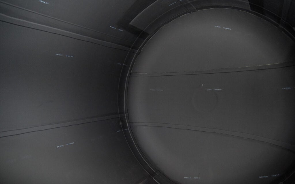
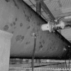
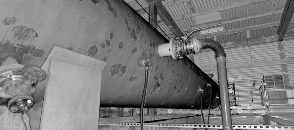
Many of these pipes are installed high above the floor or tucked into tight spaces, making accurate measurements with tape alone impractical. To address this, Abtrex works with Wadelynn Geospatial to capture high-resolution 360-degree imagery and 3D laser scans of the installed piping systems. These scans capture not only visual detail but also precise spatial data, creating a complete digital record of the pipe as it exists in place. Connections, nozzle locations, and surrounding interferences are all documented in context, providing a far more accurate reference than standard photography.
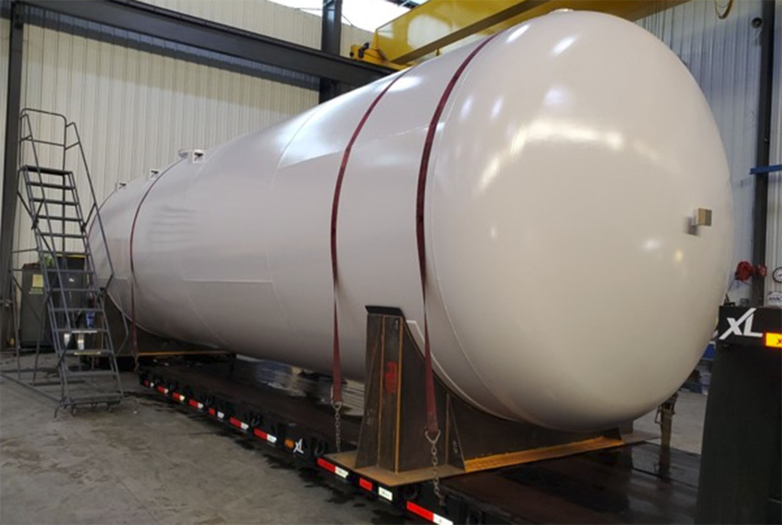
High resolution imagery of a header pipe
Step Two: 3D Scan to CAD
The collected scan data forms a unified 3D point cloud of the piping system. Using LiDAR-based scanning technology, this digital model represents the exact geometry and spatial relationships of the installation in measurable form. It allows our engineers to rotate, zoom, and inspect every section from any angle, supporting accurate understanding of existing conditions without needing to physically access every location. To further assist in the creation of a workable 3D model for fabrication, Wadelynn engineers can convert the point cloud into a rudimentary solid model in a variety of CAD formats.
While the scan provides critical dimensional insight, it’s not treated as a perfect blueprint. Measurement detail is selectively intensified in key areas, based on access and available lines of sight, to capture precise dimensions essential for fit-up and performance. Certain measurements may fall between standard pipe sizes, especially when the original installation has shifted or sagged over time. Recognizing those limitations is part of the process.
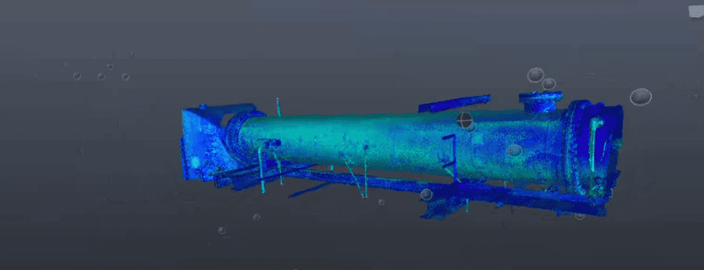
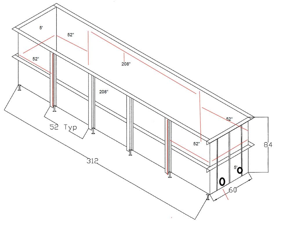
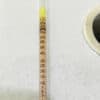
3D point cloud of a pipe
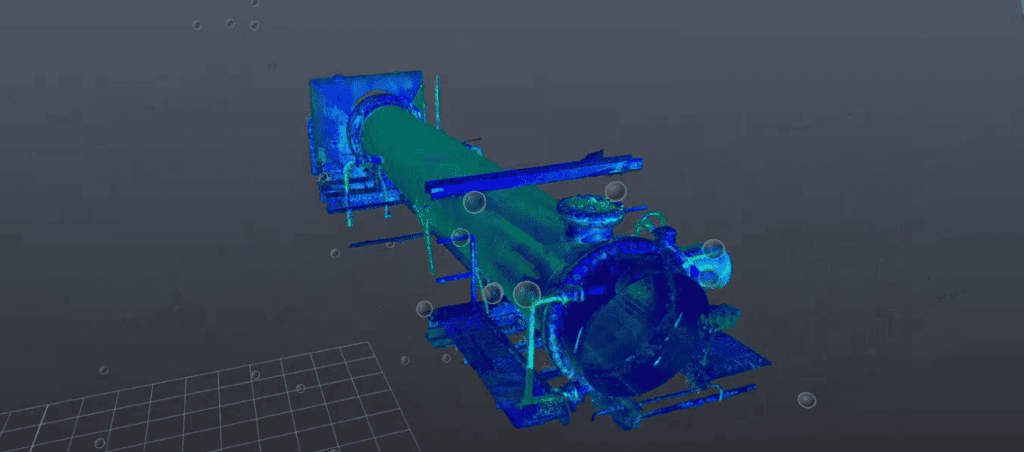
3D point cloud scan
Step Three: Where Experience Kicks In
An Abtrex engineer reviews the scan data and begins validating it against known piping standards and expected component geometries. When a measurement doesn’t align with known pipe standards, it’s flagged and checked against other reference points.
For example, flanges are typically standardized components, so their dimensions provide a reliable reference point. When a flange does not match expected ANSI standard sizing, it indicates that the system may include non-standard or internationally sourced components. The scan data helps identify and document these differences, so the final design accurately reflects what is physically installed, rather than assuming uniform standardization.
Step Four: Building the Actual Model
When the geometry is verified, the pipe is modeled in SolidWorks. The final SolidWorks model becomes the foundation for pipe fabrication, translating visual data and engineering judgment into something that can be built on the production floor, including a bill of materials. This approach allows Abtrex to produce a custom pipe that fits the system while still meeting fabrication and installation requirements.
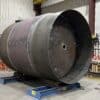
By the end of the modeling phase, the pipe is fully defined and ready for fabrication. What started without a drawing is converted into a verified pipe spool based on confirmed dimensions and standardized geometry.
When a drawing doesn’t exist, Abtrex doesn’t guess. We build the path from the field to the model, and from the model to a finished custom pipe.
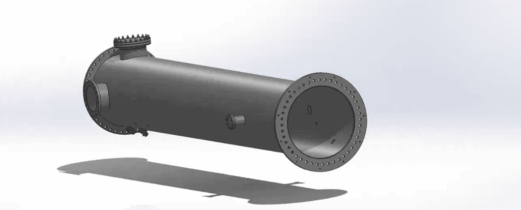
Header pipe SolidWorks model
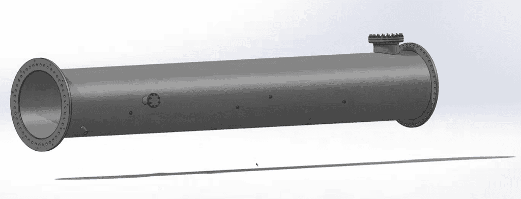
Pipe SolidWorks model
 Partner With Us for Your Next Manufacturing Project