Category

Quality Control

Rubber Lined Cistern Interior

Cold Weather Storage Considerations for Rubber Lined Tanks

By Quality Control

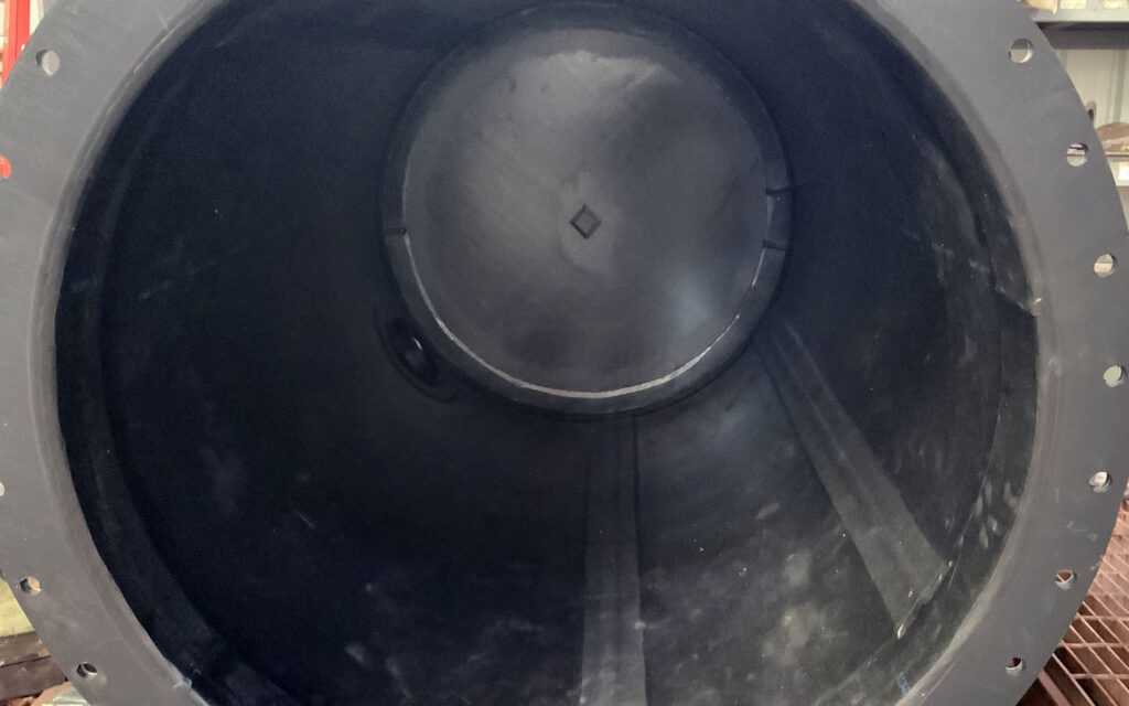
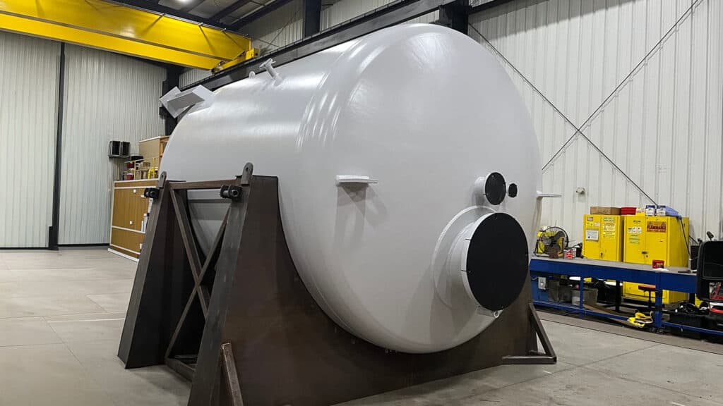
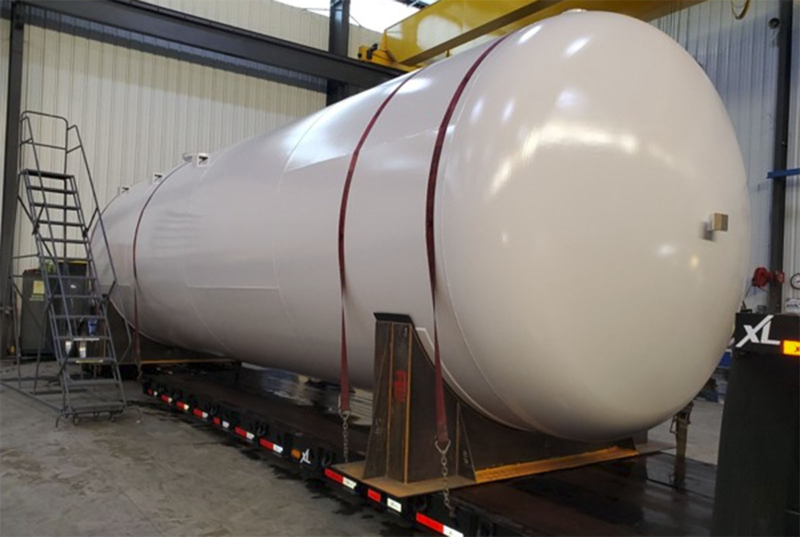
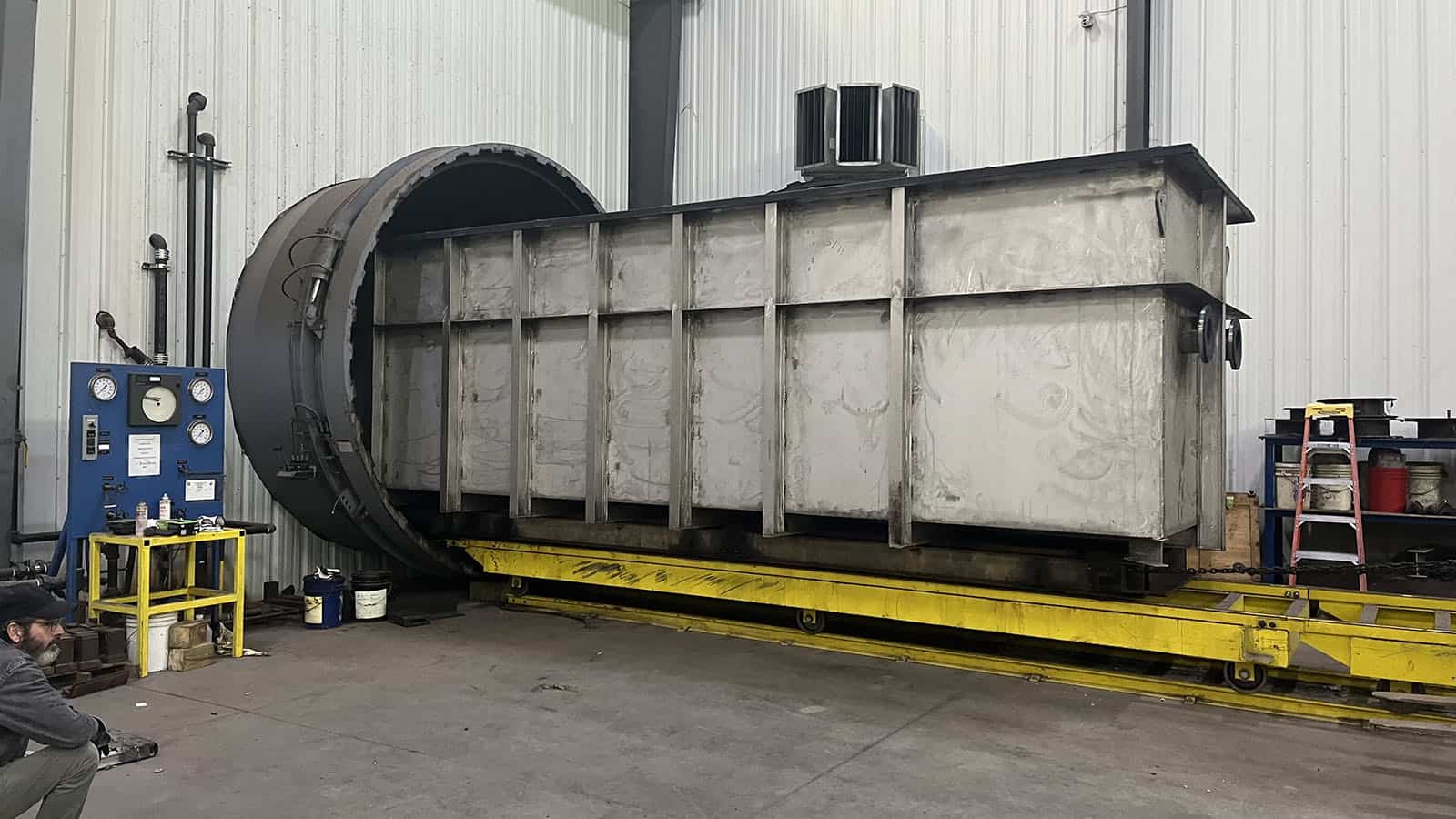
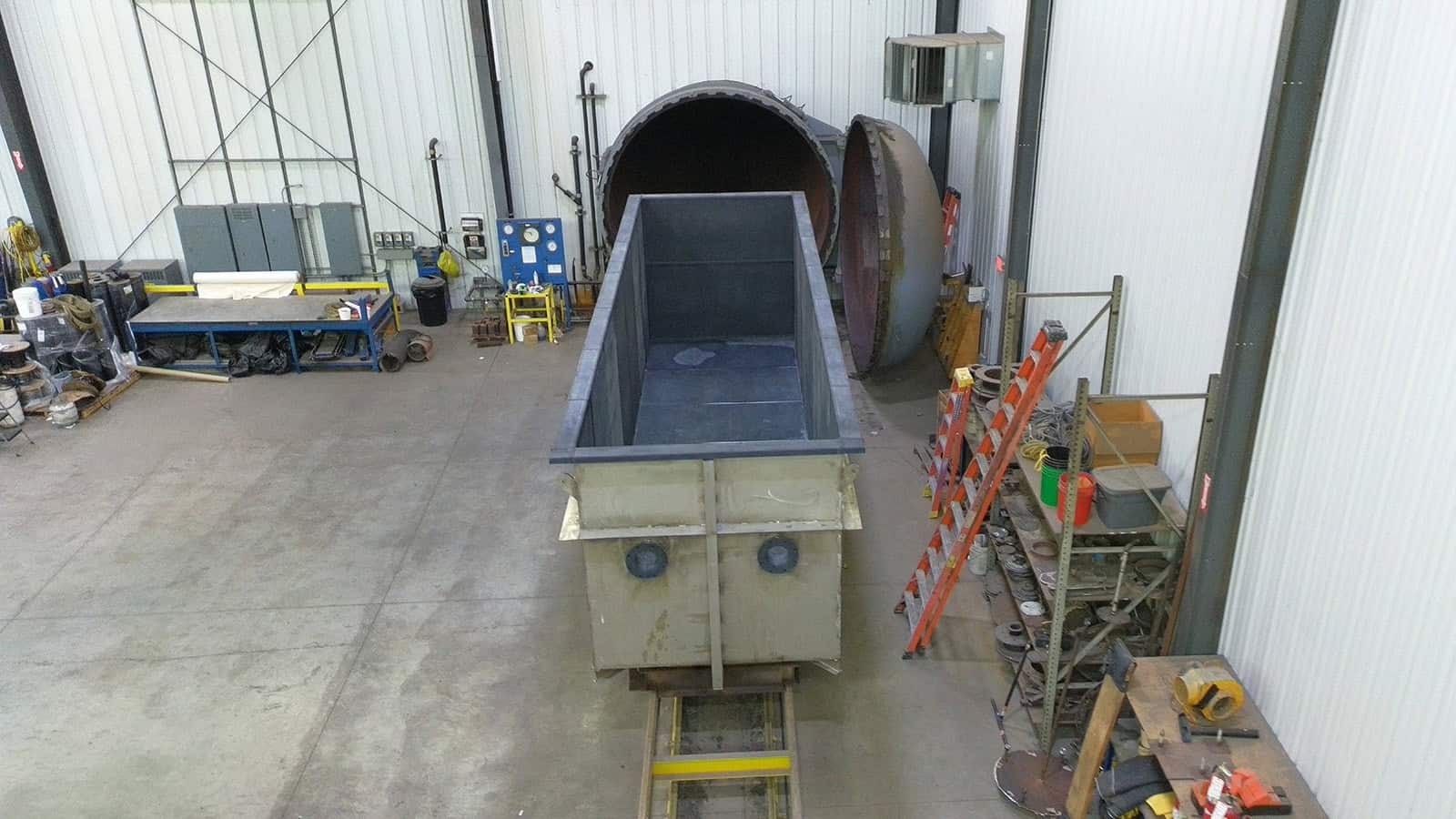
When rubber-lined equipment is specified for an application, it is typically driven by performance requirements such as chemical resistance, durability, and long-term protection of critical assets. Rubber linings are widely used in storage tanks and industrial vessels applications where high performance under specific service conditions is required. While these materials are engineered for demanding environments, their integrity and service life are strongly influenced by how the equipment is stored when it is not in operation, particularly when exposed to cold ambient temperatures.

Material behavior at low temperatures

Cold temperatures reduce molecular mobility in all elastomers, including cured natural rubber and other rubber lining materials. As temperatures decrease, rubber linings exhibit increased stiffness, higher apparent hardness, reduced flexibility, and lower impact resistance. These effects are temporary in nature but can become problematic when combined with mechanical stress, handling, or rapid temperature changes.

Cured rubber also exhibits a higher coefficient of thermal contraction than steel or other common substrates. During cold exposure, this differential shrinkage can introduce tensile stresses within the lining and at the bond interface. In hard and semi-hard linings, which are less tolerant of strain, these stresses may increase the risk of cracking, adhesion loss, edge lifting, or localized debonding, particularly under vibration or impact.

Many hard and semi-hard rubber compounds are not recommended for exposure below freezing temperatures. Some formulations may require controlled shipping, storage, or handling below approximately 32°F, with additional precautions below 20°F. Manufacturer specific compound limitations should always be reviewed when establishing storage protocols.

Storage location versus temperature exposure

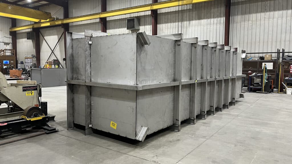
Cold-weather considerations apply wherever rubber-lined equipment is exposed to low or fluctuating temperatures. Equipment stored outdoors, in unheated warehouses, or in buildings without climate control may experience similar thermal conditions. From a technical standpoint, the response of the rubber lining is governed by temperature and thermal cycling rather than physical location.

When a rubber-lined tank that has been stored at low temperature is returned to service, introducing warm or hot process media can subject the lining to thermal shock. Rapid temperature changes may intensify stress within the lining system, particularly in areas of geometric complexity or minor surface irregularities. Features that are benign under stable ambient conditions may become stress concentrators during rapid heating.

To mitigate these risks, manufacturers consistently recommend minimizing sudden temperature changes and allowing equipment to equilibrate gradually before handling or placing it back into service.

Recommended storage and protective measures

Manufacturers of rubber linings generally provide similar guidance for cold-weather and long-term storage:

  • Store rubber-lined vessels away from direct sunlight, ozone-generating equipment, and environments subject to rapid temperature fluctuations.
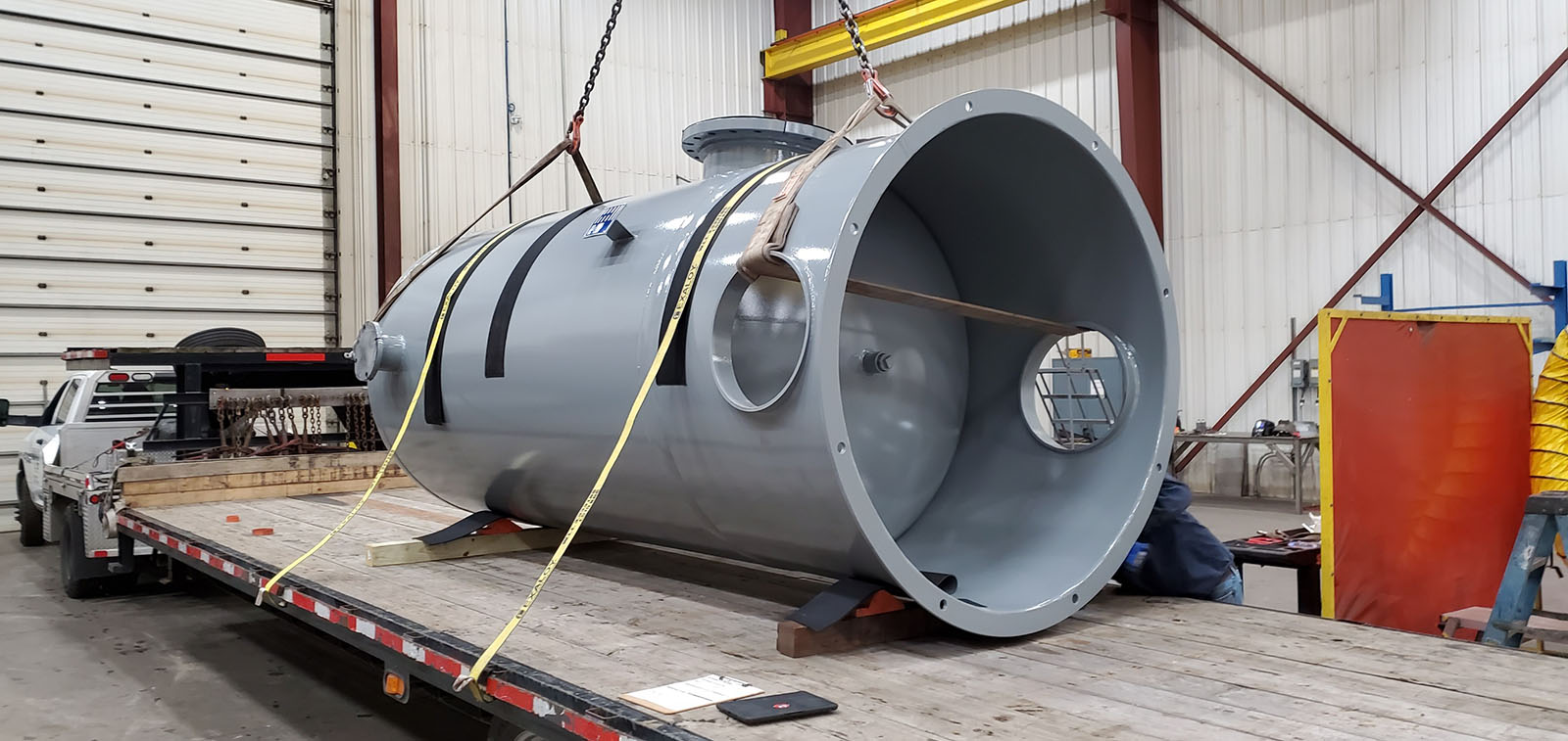
  • Protect outdoor-stored tanks with suitable poly covers or tarpaulins to reduce exposure to wind, precipitation, and rapid cooling.
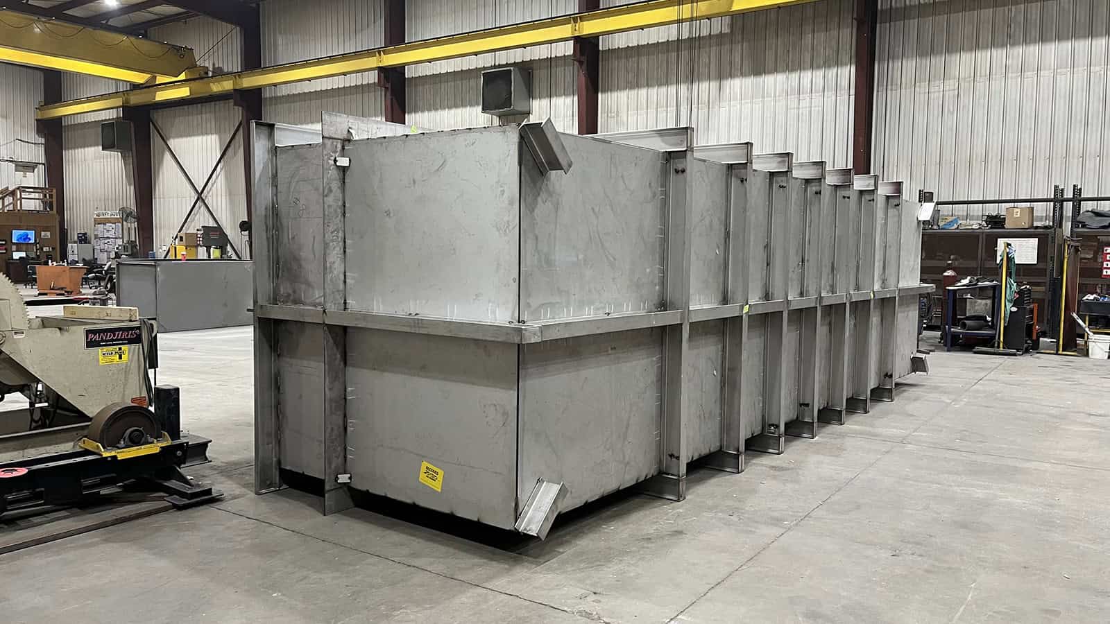
  • Hard and semi-hard rubber-lined equipment should be stored indoors whenever feasible and protected from cold climatic conditions.
  • Idle or standby rubber-lined tanks may benefit from protective measures such as a nitrogen purge or partial filling with a non-freezing solution, provided the liquid is not allowed to freeze.
  • In certain cases, surface protection using a silicone emulsion may be recommended to reduce environmental degradation during extended storage periods.

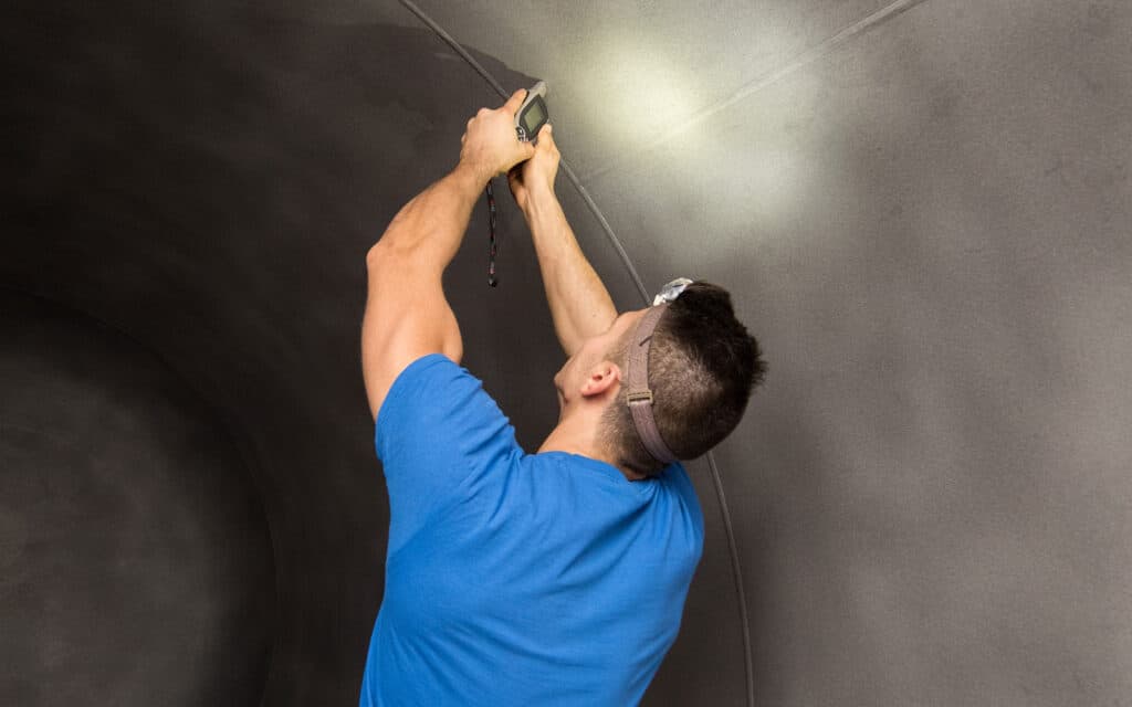
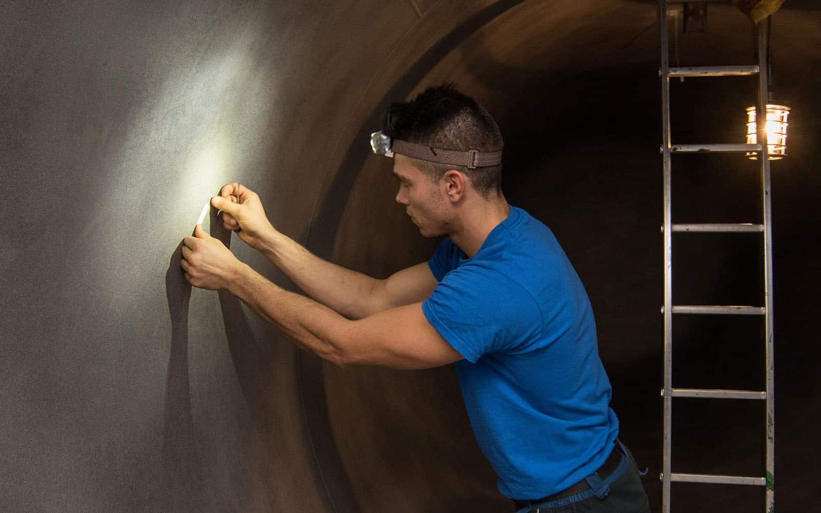
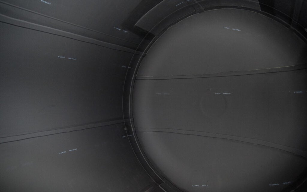
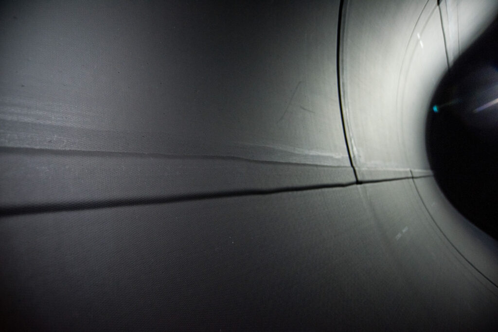
After exposure to cold storage, a detailed inspection should be conducted prior to returning the equipment to service. Inspection should focus on cracks, edge debonding, localized hard spots, and other indications of cold-related stress or loss of adhesion.

Installation and mechanical considerations

Cold-weather exposure also affects auxiliary components associated with rubber-lined equipment. Gasket selection and bolting practices are particularly important. A commonly recommended approach is to use gaskets that are approximately 10 durometer points softer than the rubber lining itself. This helps ensure adequate sealing while minimizing localized stress concentrations at flanges.

Bolt torque values and patterns should be carefully controlled and verified, especially after cold storage, to account for material stiffness changes and differential thermal contraction. Improper torque can exacerbate stress at the lining interface and reduce long-term reliability.

Preserving lining performance

Rubber linings remain a high-quality, high-performance solution for chemical service and corrosion protection when handled in accordance with manufacturer recommendations. Proper storage practices, controlled temperature transitions, and thorough inspection prior to service are essential to maintaining the intended service life of a rubber-lined tank.

By treating storage conditions as an extension of the overall service environment, operators can ensure that rubber-lined equipment continues to perform as designed- through seasonal temperature changes and throughout its operational lifecycle.

Rubber Lining Sheet

Pressure Vessel with 4 Coat System by Abtrex Industries

Abtrex Reaffirms Commitment to Quality with ASME and National Board Certification Renewal

By News, Quality Control

Abtrex has successfully completed recertification for both the National Board “R” Symbol and the ASME “U” Stamp, confirming continued compliance with applicable ASME and National Board requirements.

Abtrex has held these certifications for multiple certification cycles. The most recent recertification verifies that our Quality Control System, design, fabrication and repair procedures, inspection program, documentation practices, and personnel qualifications remain in full compliance with:

  • ASME Boiler and Pressure Vessel Code, Section VIII (ASME “U” Stamp)
  • National Board Inspection Code (NBIC)
  • NB-415 – Accreditation of “R” Repair Organizations

The ASME “U” Stamp authorizes Abtrex to design and manufacture pressure vessels in accordance with the ASME Boiler and Pressure Vessel Code. This includes full responsibility for code-compliant fabrication activities such as material control, welding and welding procedure qualifications, nondestructive examination, inspection, pressure testing, certification, and documentation.

In addition, the National Board “R” Symbol authorizes Abtrex to perform repairs and alterations to pressure-retaining equipment in accordance with NBIC requirements, including proper documentation, inspection hold points, and National Board involvement where applicable.

Successful recertification confirms Abtrex’s continued capability to serve as a qualified ASME pressure vessel manufacturer, while also providing National Board–authorized repair and alteration services under a single, audited quality system.

For questions regarding our certified capabilities or to discuss project requirements, please contact Abtrex or request a consultation with our technical team.

Pressure Vessel by Abtrex IndustriesPressure Tank by Abtrex IndustriesPressure Vessel with 4 Coat System by Abtrex Industries

Sulfuric Acid Open-top Tank

Finite Element Analysis and Smart Design Choices for Corrosion-Resistant Tanks

By Quality Control

When a coating industry customer sent an initial “sketch-level” concept for large stainless-steel tanks, our engineering team transformed the idea into a validated, build-ready design. The application involved sulfuric acid, a strong highly corrosive mineral acid with powerful dehydrating and oxidizing properties, and significant structural loads, making robust engineering essential.

Initial Tank Sketch

Initial Tank Sketch

Why Finite Element Analysis (FEA) Matters

The largest of the five open-top tanks measures 312″ L x 84″ W x 84″ D with a 9,500-gallon capacity.  The other four are 12” narrower.  The ¼” thick shells, top rim and nozzles  are all grade 316 stainless steel, and structural steel supports are 304 stainless steel. Filled with sulfuric acid (≈1.83 g/cm³), the hydrostatic pressure and a ~20,000-lb rim load demanded more than rule-of-thumb design. Abtrex design engineers used Finite Element Analysis (FEA) to simulate combined fluid, gravity, and rim loads and visualize stress and deflection throughout the structure.

FEA breaks a structure into small elements, applies loads and constraints, and calculates stress and deflection. This process allowed our team to identify overstressed regions and optimize the beam layout for safety and cost efficiency.

Design Study Results

The initial concept used six longitudinal beams, but FEA revealed excessive mid-span stress and deflection. Under combined hydrostatic pressure (increasing toward the floor) and the applied ~20,000lb rim load, color maps showed critical zones forming near the center while displacement plots indicated the top midspan bowing nearly an inch in the early iterations.

To correct this, our engineers added a central beam and redistributed supports inward from the corners, where members had behaved more like “table legs” than effective structural stiffeners, then iterated beam positions until the stress field became uniform. Animated load cases (fluid head + rim load, with floor constraints) confirmed the progression from low stress (blue) to acceptable operating levels (green) as the optimized layout engaged. The final configuration reduced peak stress to ~19,000 psi, well below the 30,000 psi yield strength, and limited deflection to 0.3 inches, even assuming a completely full tank. This optimization was crucial because stainless steel is significantly more expensive than mild steel, making material efficiency a priority.

Sulfuric Acid Open-top Tank

Sulfuric Acid Open Top Tank

Corrosion Protection

One of the five tanks receives a rubber lining to provide a protective layer against corrosive elements. Abtrex applies a ¼-inch bromobutyl rubber lining after abrasive blasting the metal surface to achieve a 2mil angular anchor profile. This process ensures proper adhesion and delivers long-term performance under high abrasion and chemical exposure. The added protection complements the stainless-steel construction, extending service life under harsh chemical and environmental conditions.

Every tank undergoes dimensional verification, 100% visual weld inspection by our in-house certified welding inspector (CWI), and liquid dye penetrant testing of shell welds. These steps, combined with Abtrex’s expertise in rubber linings, fabrication, and corrosion resistant solutions, ensure long-term reliability under a wide range of environmental conditions.

If you are ready to optimize your next project, contact the Abtrex engineering team to discuss custom-engineered solutions for stainless steel tanks, corrosion protection, and advanced design services.

Open Top Tank After Autoclave Cure

Open Top Tank After Autoclave Cure


Rubber Lined Open Top Tank

Rubber Lined Open Top Tank

Seam Types in Rubber Linings

Understanding Seam Types in Rubber Linings

By Quality Control

Seam Types in Rubber Lining Applications

In industrial environments where corrosion and abrasion are constant threats, rubber linings serve as a critical barrier to protect assets, people, and the environment. From chemical processing to mining, water treatment, and transportation, properly installed industrial linings help ensure operational safety, equipment longevity, and cost efficiency.

Selecting the right lining material, whether natural rubber or synthetic options, along with the appropriate thickness and hardness, is only part of the equation. The method of joining rubber sheets plays a vital role in the overall performance of a lining system. Poor seam construction can lead to failure, while expertly crafted joints ensure long-term protection and reliability. In this article, we explore the different seam types used in rubber lining, construction methods, and how to choose the right one for your application.

The Role of Seam Types in Rubber Lining Systems

Seams connect individual sheets of rubber during the lining process. While rubber itself is highly durable, seams can become points of vulnerability if not installed correctly. Selecting the right seam type and installation precision is essential to prevent leaks, maintain chemical resistance, and ensure the system performs under pressure.

The two most common seam styles in rubber lining are overlap joints and skive butt joints (with or without cap strips). Each has unique characteristics, construction requirements, and advantages depending on service conditions.

Overlap Seams

Overlap seams are created by skiving and overlapping the edges of two rubber sheets, typically by about two inches.

In a closed skive configuration, both the top and bottom sheets are skived usually at a 45-degree angle, with a 2″ overlap so they interlock flush, forming a seamless, tapered transition. This method is especially effective in multi-layer syntetic industrial linings containing tie gum. It helps protect the underlying plies from chemical attack and mechanical damage.

Open skive seams, which also use a 2” overlap, are typically used in single-layer natural rubber systems without tie gum. The open skives place less stress on the seam compared to closed skives and are less likely to lift during the curing process.

Closed Skive Overlap and Open Skive Overlap
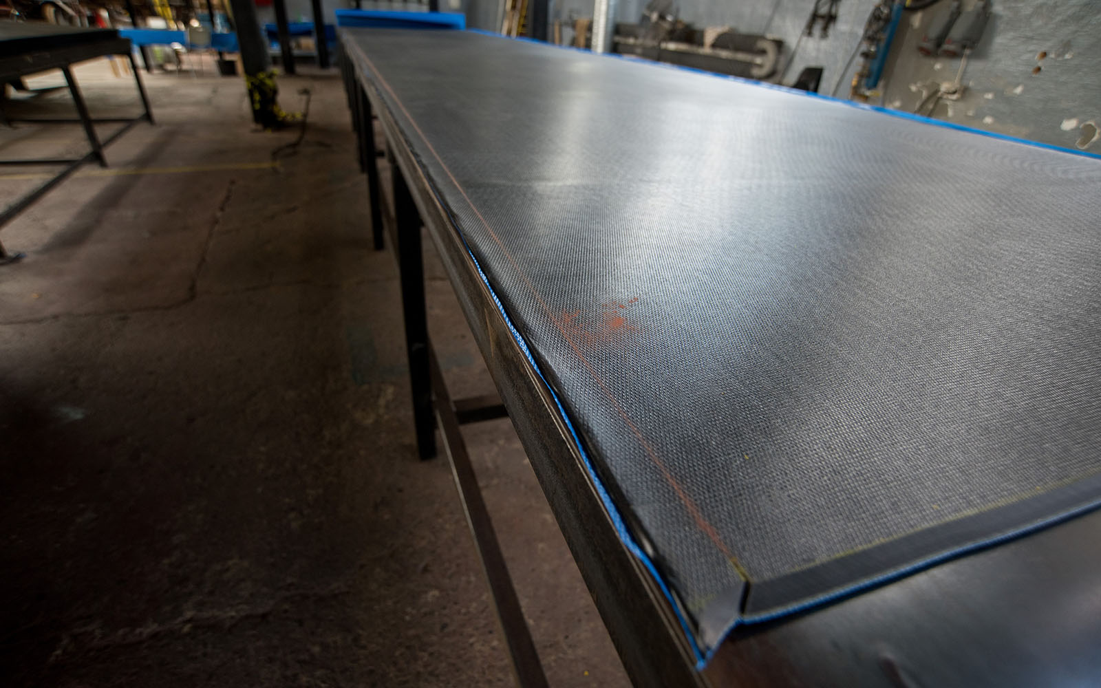
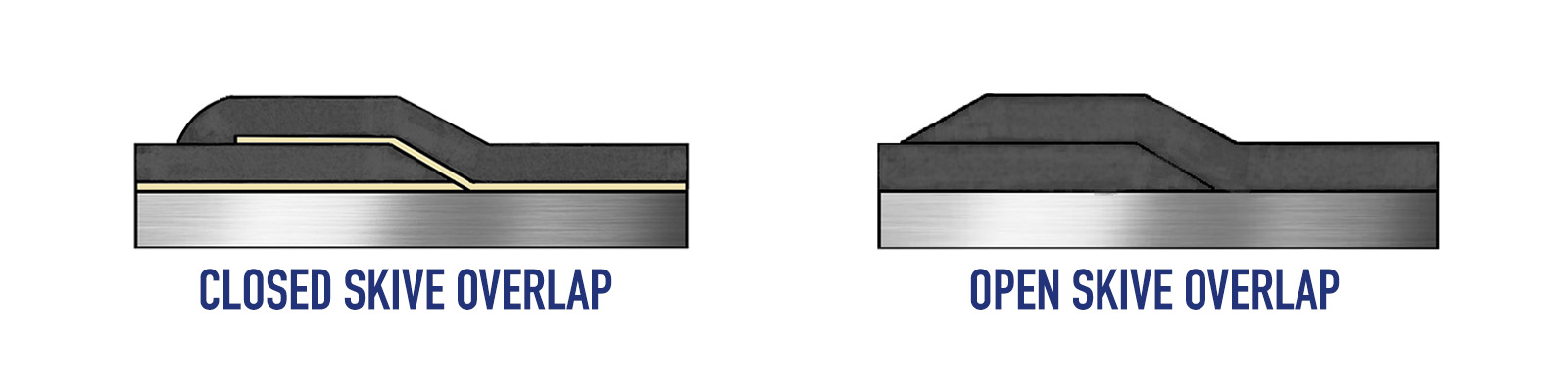
These seams are particularly effective in high-wear or high-flow environments, where durability is critical. To minimize the risk of seam lifting under flow pressure, it’s important to align the overlaps in the direction of media flow.

Overlap seams are also relatively efficient to install and require minimal additional materials. This makes them a popular choice for standard chemical and abrasive applications. Their combination of strength, protection, and ease of installation makes them a reliable solution in many industrial rubber lining projects.

Skive Butt Joint Seams

Skive butt joints are made by skiving the edges of two sheets at a 45-degree angle and butting them together without overlapping. This results in a smooth, flush surface, which can be ideal for flat areas or when clearances are tight. While this type of joint can be used on its own, it is often reinforced with a cap strip in more aggressive environments.

Butt joints without cap strips are typically faster to install and offer a clean appearance. However, they provide less chemical protection at the seam and require exact alignment and surface preparation.

Rubber Lining Seams: A Butt Joint SeamCap Strips

A cap strip is a 4 inch wide, 1/8-inch-thick strip of skived, uncured rubber applied directly over a butt joint. Its main purpose is to seal and protect the seam, particularly in highly corrosive environments such as bleach tanks. Unlike base rubber, cap strips do not contain tie gum. This makes them less chemically reactive and more suitable for aggressive chemical service.

Butt Joint with Cap StripCap strips are applied after spark testing and de-airing the butt joint, then cured along with the rest of the lining. They add an extra barrier of protection and provide a backup seal in case the primary seam begins to degrade.

Cap strips provide superior sealing in corrosive service environments, reducing the risk of air entrapment during installation. They also offer secondary protection. If the primary seam begins to degrade, the cap strip acts as an additional barrier to protect the substrate.

Choosing Between Cap Strips and Lap Joints

Using a butt joint seam with a cap strip is more expensive and time-consuming than a standard overlap joint because it involves additional materials, labor, and process steps.

Unlike a lap joint, which requires simply skiving, overlapping, and bonding two rubber sheets, a butt joint must be precisely aligned and skived edge-to-edge, spark tested, de-aired, and then covered with a separate cap strip that must also be centered, bonded, and cured with the rest of the lining. This adds extra rubber material, specialized rubber-to-rubber adhesives, and more time for careful installation. It also requires a higher skill level to ensure seam integrity, particularly in critical chemical service environments.

While cap strips provide added protection they are typically reserved for critical service environments where maximum performance is required. For most standard applications, a 2-inch overlap joint is often sufficient and preferred, as it provides reliable sealing with less complexity.

A Butt Joint Seam with Cap Strip

A Butt Joint Seam with Cap Strip

Factors Influencing Seam Type Selection

Selecting the right seam type, whether a lap joint, skive butt joint, or cap strip, plays a critical role in the performance and longevity of any rubber lining system. The decision depends on several factors, starting with the operating environment. For aggressive chemical applications like bleach or acid service, cap strips are preferred for their superior sealing and chemical resistance. In less demanding or abrasive conditions, lap joints with closed skives usually provide sufficient protection, especially when installed in the flow direction to prevent seam lifting.

The geometry of the equipment also has a direct impact on seam selection. Tight or irregular spaces may limit the practicality of overlap joints, making butt joints with cap strips a better solution.

The thickness of the rubber lining is another key factor; linings thicker than 1/4 inch can make overlaps too bulky, in which case butt joints with 1/8 inch cap strip are used to avoid excessive seam buildup. Seam types must also be compatible with the curing method and adhesive systems to ensure a strong, void-free bond during installation.

Cost and timeline are practical concerns that can influence the choice. While cap strips provide added protection, they also require more material, adhesive, and skilled labor, extending the overall installation process. Lap joints, by comparison, are faster to install and more economical, making them ideal for standard service conditions when performance demands are moderate.

Finally, customer specifications and industry standards often dictate seam selection. At Abtrex, we take all of these variables into account. Chemical and abrasive exposure, equipment geometry, liner thickness, performance goals, and compliance needs to recommend and implement the most effective seam strategy for every application.

A rubber lining is only as reliable as the way it’s applied, and that includes how its seams are constructed. Whether you choose overlap joints, skive butt joints, or cap strips, each plays a crucial role in the effectiveness of your corrosion protection system. At Abtrex Industries, our rubber liners bring decades of experience in industrial lining installation, material selection, and seam design to ensure your system operates reliably, even under the toughest conditions.

Need help choosing the right seam type for your rubber lining application? Contact Abtrex today to speak with one of our experts or request a custom quote for your next project.

Depth Micrometer Profile Testing

Surface Profile Testing

By Quality Control

Why Surface Profile Testing Is Critical for Proper Adhesion of Rubber Linings

Surface preparation is essential to promote strong mechanical and chemical bonding between the substrate and rubber lining. It is the most fundamental step in the lining process, ensuring that the corrosion protection system performs effectively. The lining material, whether natural rubber or a synthetic blend, must meet standards for thickness and hardness. However, rubber lining systems, even when specified correctly for the service environment, won’t perform well without proper surface preparation.

An improperly prepared metal surface is one of the leading causes of corrosion barrier failure. If the specified surface profile and cleanliness level are not achieved the lining may not adhere properly. Simply put, improper surface preparation can shorten the service life of the lining and reduce its corrosion protection capabilities.

At Abtrex Industries, every rubber lining application begins with cleaning, blasting and/or mechanical scarification process, followed by inspection of the surface profile. This ensures each project meets our strict internal standards and industry best practices.

Surface Profile Testing Methods

Surface profile is quantified by measuring the depth of the valleys in relationship to the top of the peaks. It tests the roughness and texture of a substrate after abrasive blasting by measuring the distance between the highest peaks and the lowest valleys. The ‘anchor’ profile ensures the lining material adheres to the substrate.

One of the most widely recognized industrial standards, ASTM D4417-20 ‘Standard Test Methods for Field Measurement of Surface Profile of Blast Cleaned Steel’ outlines four methods to measure surface profile:

  • Method A – Visual Comparator – Compares the blasted surface to pre-made reference plates with known roughness values
  • Method B – Depth Micrometer – Uses a fine conical probe to measure the distance from peaks to valleys
  • Method C – Replica Tape – Involves pressing a special foam replica tape against the substrate to create a reversed image of a surface, which is then measured with micrometer
  • Method D – Electronic Profilometer – Uses electronic instrument to scan the surface and generate a digital profile of its texture

Surface Preparation and Testing Process

Before the metal substrate can be examined the surface must be thoroughly cleaned, free from dust or blast media debris. Once cleaned, locations for representative samples must be selected. The SSPC-PA 17-2020 ‘Procedure for Determining Conformance to Steel Profile/Surface Roughness/Peak Count Requirements’ specifies identifying three 6×6 inch areas for each blast unit used per work shift.

Depth Micrometer Profile Testing

Depth Micrometer Profile Testing

Before using the depth micrometer, the instrument must be zeroed out on a glass zero plate and verified on a metal shim to ensure accuracy. During testing, the gauge is placed perpendicularly on the blasted surface and slightly pushed downwards, allowing the conical probe to measure the distance between the surface peaks and valleys. The result is displayed on a digital screen of the measurement instrument.

Depth Micrometer

Per D4417-20, there are (3) acceptable parameters for measurement quantities:

  1. Measure at a sufficient number of locations to characterize the substrate as specified or how many readings are agreed upon between the parties involved.
  2. For each selected area, ten readings must be taken. Record the maximum values from each location, then determine the average from all locations.
  3. Take ten readings at each location and average those readings.  Then determine the average from all three locations.

It must be noted that ‘outliers’ will occur when taking digital depth micrometer readings.  You simply ‘toss’ those readings and replace them with measurements that are considered to be in the specified range.

Replica Tape Surface Profile Testing

Replica Tape Surface Profile Testing

The replica tape method involves pressing the Testex tape onto the cleaned, blasted surface. The tape consists of a compressible foam layer bonded to a 2-mil mylar film. When pressed against a roughened steel substrate, the foam collapses and forms an reverse impression of the surface profile.

Depending on the expected roughness, one of four tape grades is selected to ensure accurate measurement:

  • Coarse Minus – 0.5-0.8 mils
  • Coarse – 0.8-2.5 mils
  • X-Coarse – 1.5-4.5 mils
  • X-Coarse Plus – 4.0-5.0 mils

After the appropriate tape is chosen, a section is cut from the roll and applied to the cleaned, blasted surface with the foam side facing down. Next, the tape is burnished with the rounded tip of a plastic or metal stick. This action allows the foam to penetrate the valleys of the texture and create a reverse image of the surface profile. When the backing turns a uniform gray, it indicates that the profile is replicated. At that point, the tape can be removed and inserted into a spring-loaded micrometer.

Tested Micrometer for Replica Tape

To account for the Mylar backing of the replica tape, it is standard practice to adjust the gage reading by subtracting 2 mils. A common practice is to ‘dial back’ the gage to ‘8’. For accuracy, at least two readings should be taken at each location.

One of the key benefits of this method is that the replica tape serves as a durable, long-term archival record of the surface condition, making it ideal for future reference and quality documentation.

Surface profile testing is a critical step in securing strong adhesion and reliable performance of rubber linings. At Abtrex, we utilize precise measurement methods—including depth micrometers and replica tape—to ensure that every substrate is prepared to the highest standard. This not only enhances mechanical bonding but also protects the integrity of the lining system over time.

By adhering to industry standards such as ASTM D4417 and SSPC-PA 17, Abtrex delivers rubber lining solutions that stand up to the toughest industrial environments and provide lasting corrosion protection.

Contact us to discuss your project needs and discover how we ensure your equipment is built and protected to the highest standards against chemical and abrasion damage.

Stitcher for protective rubber lining

Essential Hand Tools for Corrosion Resistant Rubber Linings

By Quality Control

Rubber linings are an excellent solution for handling elevated concentrations of acids and other highly corrosive environments. Thanks to their strong abrasion- and corrosion-resistant properties, rubber linings are widely used in industries such as mining, steel production, wastewater treatment, and chemical processing.

Natural rubbers and other rubber compounds are essential for preventing damage to equipment from the severe service conditions commonly encountered in industrial environments. The lining materials play a critical role in safeguarding tanks, piping, and other process equipment, making it essential for installation to meet the highest standards to ensure strong adhesion and prevent potential leaks.

The installation of rubber lining is a manual and precise process that requires specific skills and experience to apply a durable, long-lasting barrier. Using specialized hand tools is essential to achieve the precision and safety needed to ensure the lining is free of any holidays or voids to create an impermeable, homogeneous barrier, effectively preventing corrosion for years to come. Hand tools used by rubber liners are quite unique and specific to their roles.

Rubber Lining Hand Rollers and Stitchers

Hand rollers
Hand rollers come in two main types: hard and soft, each available in various sizes to suit different applications. Hard, wider rollers are ideal for large, flat surfaces, ensuring efficient coverage and pressure across bigger areas. In contrast, soft, smaller rollers are well-suited for tighter, curved spaces, corner joints, and nozzles, where flexibility and precision are needed.

Rollers play a crucial role in pushing out trapped air pockets from between the rubber lining and the substrate. This helps ensure strong adhesion by removing air pockets that can expand during the curing process, causing blisters between the rubber and the surface. This is a key process that creates a reliable bond between the lining material and the substrate, enhancing its durability and creating a highly resistant corrosion barrier.

Abtrex Industries Team uses a hand roller for natural rubber lining

Hand roller for rubber lining

Stitchers
At Abtrex, we utilize three types of stitchers during the rubber lining process: regular, curved gooseneck, and long pipe stitchers. These tools feature specialized protrusions that enhance grip, preventing slippage on the rubber surface. Stitchers are essential for working in tight, uneven areas, corners, and on 2-inch laps to release trapped air bubbles from behind the rubber lining. Using a smaller stitcher ensures greater precision compared to a roller.

Stitcher for protective linings

Stitcher for protective linings

Rubber Lining Saw and Knives

Cutting with an Electric Water Saw
Large rubber lining sheets are typically cut using an electric water saw. This automated tool speeds up the cutting process, making it efficient for handling large sheets. To ensure smooth operation, the saw blade requires constant wetting, supported by an attached water reservoir that keeps the blade cool and prevents material damage.

Electric saw for cutting lining sheets

Electric saw for cutting lining sheets

Rigid Skiving Knife
Rigid skiving knives are essential for precision cutting, particularly when working with thicker rubber linings. These knives are ideal for creating precise skives along the material’s edge. Regular sharpening and spritzing with water while cutting, ensures a clean, uniform edge that supports the highly resistant to corrosion qualities of rubber linings.

Flexible Skiving Knife
Flexible skiving knives are better suited for thinner rubber linings, allowing for more precise skives. Achieving a proper skive manually can be challenging and requires holding the knife at a specific angle. The flexibility of these knives helps maintain the correct angle, ensuring consistent and accurate cuts.

Hot Knife for Flange Bolt Holes
A hot knife is indispensable for cutting flange bolt holes in rubber linings. A small propane torch is used to heat the blade, which retains a temperature of up to 300 degrees for approximately 1.5 minutes. This allows for clean and precise cuts without damaging the surrounding material, which is crucial when working in highly corrosive environments that require superior material integrity.

Skiving knife for cutting natural rubber

Skiving knife for cutting rubber